
In the previous posts of this series, we covered the fundamentals of AWS Cloud WAN, east-west traffic inspection using Network Function Groups and the send-via action, and how to migrate an existing Transit Gateway network to Cloud WAN. In this final post, we address one of the most common challenges in multi-account AWS environments: centralized internet egress.
AWS Cloud WAN offers a declarative alternative through the send-to service insertion action. By adding a single block to the Core Network Policy, Cloud WAN automatically injects the 0.0.0.0/0 route in every workload segment pointing to a centralized egress Network Function Group. Adding a new region or segment requires no manual routing changes.
send-to vs send-via#
In the second post of this series, we explored Network Function Groups and the send-via action for east-west traffic inspection. The send-to action follows the same model but is designed for north-south traffic — traffic that leaves the Cloud WAN network entirely.
The key difference is what happens after the traffic passes through the NFG:
send-via | send-to | |
|---|---|---|
| Traffic type | East-west (VPC ↔ VPC) | North-south (VPC → internet) |
| Returns to Cloud WAN | Yes | No |
mode parameter | single-hop / dual-hop | Not applicable |
| Default route injected | No | 0.0.0.0/0 in the segment |
| Use case | Inter-segment inspection | Centralized egress |
With send-to, traffic exits the Cloud WAN backbone through the egress VPC and does not return. The response traffic from the internet enters through the Internet Gateway, passes through Network Firewall for inspection, and is routed back to the originating instance via Cloud WAN — but that return path is handled by static routes in the egress VPC, not by the service insertion policy.
The Core Network Policy configuration is straightforward:
{
  "segment-actions": [
    {
      "action": "send-to",
      "segment": "prod",
      "via": {
        "network-function-groups": ["egress"]
      }
    }
  ]
}
Cloud WAN automatically injects a 0.0.0.0/0 static route in the prod segment pointing to the egress NFG. No additional routing configuration is needed in the segment itself.
Architecture#
The pattern consists of three layers. The key insight is that workload VPCs have no Internet Gateway — they cannot reach the internet directly. The only exit point is Cloud WAN, which redirects all outbound traffic to a centralized egress VPC per region.
Workload VPCs attached to the prod segment. They have no Internet Gateway — all outbound traffic is routed to Cloud WAN via a default route.
Cloud WAN Core Network with a prod segment and an egress Network Function Group. The send-to service insertion policy redirects all internet-bound traffic from prod to the egress NFG.
Egress VPCs attached to the egress NFG, one per region. Each egress VPC contains three subnet tiers: an attachment subnet (where Cloud WAN connects), a firewall subnet (AWS Network Firewall endpoint), and a public subnet (NAT Gateway + Internet Gateway).
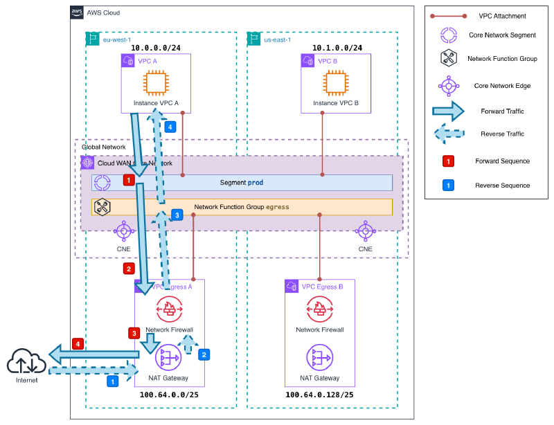
Traffic flow#
Let’s trace the path of a packet from a workload instance to the internet and back.
Outbound:
The instance sends a packet destined for the internet. The subnet route table has a single default route pointing to Cloud WAN:
0.0.0.0/0 → Core Network.The packet arrives at the
prodsegment in Cloud WAN. Thesend-topolicy has injected a static default route pointing to theegressNFG attachment in the same region. The segment route table foreu-west-1looks like this:CIDR Destination Type 0.0.0.0/0Egress-A (NFG) STATIC 10.0.0.0/24VPC-A PROPAGATED 10.1.0.0/24prod / us-east-1 PROPAGATED The packet is forwarded to the egress VPC attachment subnet.
The attachment subnet route table sends all traffic to the Network Firewall endpoint:
0.0.0.0/0 → NFW endpoint.Network Firewall inspects the packet and forwards it to the firewall subnet route table, which points outbound traffic to the NAT Gateway:
0.0.0.0/0 → NAT GW.The NAT Gateway performs Source NAT (SNAT): it replaces the instance’s private IP with its own Elastic IP and records the translation in its connection table. The packet is then forwarded to the Internet Gateway, which delivers it to the internet. The source IP seen externally is the NAT Gateway’s Elastic IP. When the response arrives, the NAT Gateway uses its connection table to reverse the translation and forward the packet back to the correct private IP — Cloud WAN is not involved in this step.
Return:
The NAT Gateway receives the response from the internet via the Internet Gateway and forwards it to the firewall subnet. The public subnet route table sends RFC1918 traffic back through the Network Firewall endpoint:
10.0.0.0/8 → NFW endpoint.Network Firewall inspects the return packet and forwards it to the firewall subnet. The firewall subnet route table routes RFC1918 traffic back to Cloud WAN:
10.0.0.0/8 → Core Network.The NFG route table has the workload VPC CIDRs propagated from the segment attachments:
CIDR Destination Type 10.0.0.0/24VPC-A PROPAGATED 10.1.0.0/24egress / us-east-1 PROPAGATED Cloud WAN forwards the packet to the correct workload VPC, which delivers it to the instance.
This is why the return path works without a
send-topolicy in reverse: Cloud WAN does not need one. The NFG has the workload CIDRs propagated automatically from the segment attachments, so it knows exactly where to forward the response. Thesend-topolicy only controls the outbound direction — from the segment to the NFG. The return is handled by normal route propagation.
Note: If you inspect the NFG route table, you will notice a route pointing to the egress attachment in the other region — for example, 10.1.0.0/24 → egress / us-east-1 in the eu-west-1 NFG. This route exists because Cloud WAN propagates all workload CIDRs into every NFG edge, regardless of where the egress VPC for that CIDR is located. Under normal operation it carries no traffic — instances in eu-west-1 exit through the eu-west-1 NAT Gateway and responses return the same way. This route would only be used if the eu-west-1 egress attachment were unavailable, in which case Cloud WAN would forward the return traffic across the backbone to the us-east-1 egress VPC — exactly the cross-region scenario described in the limitations section.
Additionally, the NFG route table only contains workload VPC CIDRs — it does not have a default route. This is by design: NFG route tables are fully managed by Cloud WAN and cannot be modified manually. The send-to policy handles the outbound path; the return path relies on the propagated workload CIDRs.
Demo#
Here is the Terraform code to deploy this architecture in your own AWS account:
The demo deploys two workload VPCs (one in eu-west-1, one in us-east-1) connected to a prod segment, and two egress VPCs attached to the egress NFG. Each egress VPC has an AWS Network Firewall endpoint configured with an allow-all policy for demo purposes, and a NAT Gateway for internet access. Workload instances have no Internet Gateway in their VPC and are accessible exclusively via AWS Systems Manager Session Manager.
terraform destroy when you are done.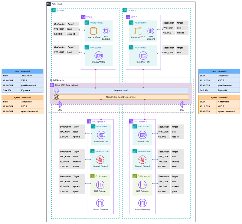
To deploy:
terraform init
terraform apply
Once deployed, connect to each instance via SSM Session Manager and verify that outbound traffic exits through the regional NAT Gateway. The instance IDs and expected NAT Gateway IPs are available in the Terraform outputs:
terraform output# Instance A (eu-west-1)
aws ssm start-session --target <instance-a-id> --region eu-west-1
sh-5.2$ curl https://checkip.amazonaws.com
108.128.39.93The returned IP should match the nat-gateway-a-ip output from Terraform — confirming that the instance has no direct internet path and all traffic flows through the centralized egress VPC.
# Instance B (us-east-1)
aws ssm start-session --target <instance-b-id> --region us-east-1

sh-5.2$ curl https://checkip.amazonaws.com
3.225.50.74
Each region uses its own NAT Gateway, as expected. Traffic never crosses regions to reach the internet.
To clean up:
terraform destroyConsiderations and limitations#
send-to applies to the entire segment. There is no way to exclude specific attachments within the same segment from the egress policy. If you need some VPCs to have direct internet access and others to go through centralized egress, they must be in separate segments. Additionally, if your prod segment has attachments in multiple regions but the egress NFG only has a VPC in one of them, Cloud WAN will route traffic from the uncovered regions across the backbone to the available egress VPC — adding latency and inter-region data transfer costs. Always deploy an egress VPC in every region where your workload attachments are located.
NFW firewall policy is regional. AWS Network Firewall policies are regional resources. You cannot reference a firewall policy from a different region — each firewall requires its own policy in the same region. If you are deploying egress VPCs across multiple regions, make sure to create a separate firewall policy in each one.
send-to does not apply to on-premises traffic. The default route injected by send-to covers internet-bound traffic, but traffic towards on-premises destinations (via VPN or Direct Connect) follows normal BGP-learned routes. If you need to inspect on-premises-bound traffic, you need send-via instead.
One egress VPC per region. NFGs are regional constructs within Cloud WAN. Each region where you have workload attachments needs its own egress VPC in the NFG. Attempting to use a single egress VPC across regions would route all traffic through one region before exiting — increasing latency and NAT Gateway data processing costs significantly.
Cost comparison with Transit Gateway egress pattern. The centralized egress pattern with Transit Gateway requires static route maintenance across all TGW route tables. With Cloud WAN, the routing is automatic, but the base infrastructure cost is higher:
| TGW + Egress VPC | Cloud WAN + Egress VPC | |
|---|---|---|
| Core network cost | ~$0.05/h per attachment | $0.50/h per edge location |
| Egress VPC cost | NAT GW + NFW | NAT GW + NFW |
| Route maintenance | Manual | Automatic |
| Multi-region consistency | Manual | Policy-driven |
For single-region deployments, Transit Gateway is almost certainly more cost-effective. For multi-region architectures already using Cloud WAN, the send-to pattern eliminates operational overhead at no additional infrastructure cost beyond the egress VPCs themselves.
Wrapping up#
The send-to service insertion action completes the Cloud WAN toolkit for traffic control. Combined with send-via for east-west inspection (covered in the second post of this series), it provides a fully declarative approach to both internet egress and inter-segment inspection — with Cloud WAN handling all route propagation automatically.
The practical benefit over the traditional Transit Gateway pattern is not the cost — it is the operational simplicity. Adding a new segment or a new region to the network requires a policy change, not a round of manual route table updates across multiple Transit Gateways. For teams managing complex multi-account, multi-region environments, that difference compounds over time.
This post closes the AWS Cloud WAN series. We have covered the full journey: from the fundamentals of the service, through security inspection, migration from Transit Gateway, and finally centralized egress. The four demo repositories are publicly available on Codeberg if you want to explore any of them.