

When working in distributed global network environments, one of the key aspects to consider is traffic inspection. This becomes particularly important when, in addition to having multiple environments, we also have connectivity with third parties and want to maintain effective control over the traffic entering and leaving our network.
One of the main services provided by AWS for inspecting traffic in complex network environments is AWS Network Firewall. In this second post of the series on AWS Cloud WAN, we will explore how we can leverage the features of this service to inspect traffic with AWS Network Firewall.
Before diving into the topic, it is necessary to familiarize ourselves with a new component that we did not cover in the previous post: Network Function Groups.
Network Function Groups#
Network Function Groups (NFG) are a type of special segment. Similar to regular segments (Core Network Segments), an NFG consists of a set of attachments; however, these attachments are specialized in networking or security functions. Therefore, an NFG can be used for traffic inspection functions, but also for outbound traffic aggregation functions, such as centralized egress VPCs.
Let’s look at the key differences between a Core Network Segment and a Network Function Group.
| Core Network Segment | Network Function Group |
|---|---|
| Segments are isolated routing domains. Attachments can be associated with full control over the routes within the segment and between segments. | NFGs have their own routing tables. These routing tables are automatically propagated (with next-hop redirections) based on the service insertion configuration defined in the Core Network Policy. Despite having full visibility of these routes, they cannot be added, deleted, or shared in any way. |
| When you associate an attachment with an AWS Cloud WAN segment, the VPC CIDRs and/or dynamic routes will be propagated into the corresponding segment’s route table. | When you associate an attachment with a NFG (Network Function Group), the VPC CIDRs and/or dynamic routes will not be propagated into the NFG route table. |
Service insertions#
As we have seen, NFGs allow us to group the network functions needed to perform traffic inspection (for example, VPCs), but we need a way to indicate to the rest of our global network how to redirect traffic through these functions. This is where service insertions come into play, which are nothing more than segment actions applied to NFGs.
Through service insertions, we can redirect traffic within the same segment or between segments to pass through, for example, a VPC with an AWS Network Firewall endpoint.
There are two main modes of inspection:
North-south traffic inspection, where traffic flows from our global network to an egress VPC for inspection and then out to the internet.
East-west traffic inspection, where traffic flows between attachments in our global network. In this case, the inspection can be done in two ways: either between attachments located in different segments —for example, when traffic flows from the production segment to the development segment— or within the same segment.
The configuration of service insertions is done in the Core Network Policy, in the same block that configures the segment actions segment-actions. To do this, we will use the parameters action and mode.
For the first case, north-south traffic, the action parameter will be set to sent-to. This action sends the traffic to the inspection VPC and then out to the internet or on-premise, depending on the case. In this case, the traffic does not return to AWS Cloud WAN.
For the second case, east-west traffic, the action parameter will be set to sent-via. This action sends the traffic to the inspection VPC and then redirects it to its destination, for example, another VPC.
When using the sent-via action, we can choose how the traffic will be redirected before reaching its final destination with the mode parameter. The values can be:
single-hop: The traffic passes through a single inspection attachment, which can be in either the source region or the destination region. By default, the source region attachment is used, though it can be configured.dual-hop: The traffic passes through inspection attachments in both the source and destination regions.
For more complex configurations, I recommend checking the reference on Core network policy version parameters in AWS Cloud WAN.
Example Configuration#
To better illustrate how to apply these configurations, an example Core Network Policy is provided.
{
  "version": "2021.12",
  "core-network-configuration": {
    "asn-ranges": [
      "64512-64555"
    ],
    "edge-locations": [
      {
        "asn": 64512,
        "location": "eu-west-1"
      },
      {
        "asn": 64513,
        "location": "us-east-1"
      }
    ],
    "vpn-ecmp-support": false
  },
  "segments": [
    {
      "isolate-attachments": false,
      "name": "segmentA",
      "require-attachment-acceptance": false
    },
    {
      "isolate-attachments": false,
      "name": "segmentB",
      "require-attachment-acceptance": false
    }
  ],
  "network-function-groups": [
    {
      "name": "inspection",
      "require-attachment-acceptance": false
    }
  ],
  "attachment-policies": [
    {
      "rule-number": 100,
      "action": {
        "association-method": "tag",
        "tag-value-of-key": "segment"
      },
      "conditions": [
        {
          "key": "segment",
          "type": "tag-exists"
        }
      ]
    },
    {
      "rule-number": 200,
      "action": {
        "add-to-network-function-group": "inspection"
      },
      "conditions": [
        {
          "key": "inspection",
          "type": "tag-exists"
        }
      ]
    }
  ],
  "segment-actions": [
    {
      "action": "send-via",
      "mode": "dual-hop",
      "segment": "segmentA",
      "via": {
        "network-function-groups": [
          "inspection"
        ]
      },
      "when-sent-to": {
        "segments": [
          "segmentB"
        ]
      }
    }
  ]
}
In this policy, two segments are defined: segmentA and segmentB, along with their corresponding attachment-policies.
The policy also defines a Network Function Group called inspection. A rule is also defined in the attachment-policies for associating the inspection VPCs when they are added.
Finally, in the segment-actions block is where the Service Insertion is configured. In this case, since we are performing east-west inspection, we indicate this with the parameter "action": "send-via". Additionally, we will perform inspection in both the source and destination regions, so we reflect this in the policy with the parameter "mode": "dual-hop".
To indicate where the inspection attachments are located, we use the via parameter, where we specify the NFG we defined earlier.
The when-sent-to parameter helps us indicate when to perform the inspection based on the destination. In this case, when the traffic is directed towards segmentB. If we needed to perform the inspection for any destination segment, we could simply indicate this with an asterisk: "when-sent-to": {"segments": ["*"]}.
segmentA and the destination is segmentB, since AWS Cloud WAN generates routes to maintain traffic symmetry, the inspection will also occur when the source is segmentB and the destination is segmentA.Demo#
As always, the best way to consolidate these concepts is through a demo.
Here you can access the demo code to deploy it in your own account:
Let’s go for it.
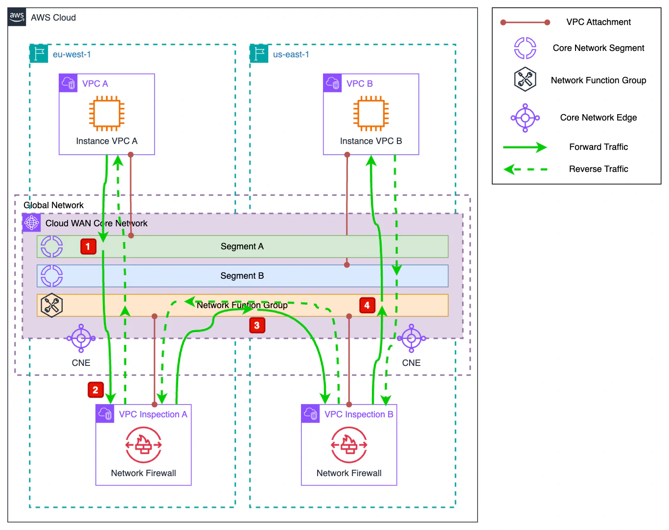
In this demo, we will see how to redirect east-west traffic between Instance A and Instance B so that it passes through inspection VPCs in both the source and destination regions. These inspection VPCs have an AWS Network Firewall Endpoint. Since this is a demo, the corresponding Network Firewall Policy allows all traffic.
Let’s see how it behaves:
Outbound traffic from Instance A reaches the Core Network via
segmentA. The routes applied tosegmentAin theeu-west-1region are as follows:CIDR Destination Route Type 192.168.1.0/25VPC A PROPAGATED 192.168.1.128/25Inspection A PROPAGATED Since the destination of the connection is Instance B with IP
192.168.1.159, the route that applies is192.168.1.128/25, which redirects the traffic to the Inspection A VPC.Once the traffic reaches the Inspection A VPC, it is evaluated by Network Firewall and returned to the Core Network.
In this case, the traffic passes through the Network Function Group which has the following routes in the
eu-west-1region:CIDR Destination Route Type 192.168.1.0/25VPC A PROPAGATED 192.168.1.128/25Inspection B PROPAGATED The route to apply is still
192.168.1.128/25, which in this case redirects the traffic towards Inspection B.After repeating the same inspection operation, this time in the
us-east-1region, the traffic again passes through the NFG. In this case, the routes it has forus-east-1are:CIDR Destination Route Type 192.168.1.0/25Inspection A PROPAGATED 192.168.1.128/25VPC B PROPAGATED By applying the route
192.168.1.128/25, this time the traffic is directed to its final destination, VPC B, and thus reaches Instance B.
Once we have seen the path that the traffic will follow, let’s deploy the infrastructure and conduct the empirical test.
terraform init
terraform apply
Once deployed, we verify that Instance B, located in the us-east-1 region and associated with segmentB, can be reached from Instance A, which is in the eu-west-1 region and part of segmentA.
Connect to Instance A via SSM Session Manager. Once connected, run a
pingcommand to Instance B.sh-5.2$ uname -a Linux ip-192-168-1-35.eu-west-1.compute.internal 6.1.134-152.225.amzn2023.aarch64 #1 SMP Wed May 7 09:10:22 UTC 2025 aarch64 aarch64 aarch64 GNU/Linux sh-5.2$ ping 192.168.1.159 PING 192.168.1.159 (192.168.1.159) 56(84) bytes of data. 64 bytes from 192.168.1.159: icmp_seq=1 ttl=119 time=80.1 ms 64 bytes from 192.168.1.159: icmp_seq=2 ttl=119 time=71.0 ms 64 bytes from 192.168.1.159: icmp_seq=3 ttl=119 time=70.9 ms 64 bytes from 192.168.1.159: icmp_seq=4 ttl=119 time=70.9 ms 64 bytes from 192.168.1.159: icmp_seq=5 ttl=119 time=70.9 ms 64 bytes from 192.168.1.159: icmp_seq=6 ttl=119 time=70.9 ms 64 bytes from 192.168.1.159: icmp_seq=7 ttl=119 time=70.9 ms ^C --- 192.168.1.159 ping statistics --- 7 packets transmitted, 7 received, 0% packet loss, time 6007ms rtt min/avg/max/mdev = 70.910/72.247/80.133/3.219 msAs we can see, Instance B is successfully reached from Instance A without any issues. Additionally, if desired, you can modify the Firewall Policy to block the traffic and verify that it indeed passes through it.
sh-5.2$ ping 192.168.1.35
PING 192.168.1.35 (192.168.1.35) 56(84) bytes of data.
^C
--- 192.168.1.35 ping statistics ---
23 packets transmitted, 0 received, 100% packet loss, time 22892ms
Now, connect to Instance B using SSM Session Manager. Once inside, run a
pingcommand to Instance A.sh-5.2$ uname -a Linux ip-192-168-1-159.ec2.internal 6.1.134-152.225.amzn2023.aarch64 #1 SMP Wed May 7 09:10:22 UTC 2025 aarch64 aarch64 aarch64 GNU/Linux sh-5.2$ ping 192.168.1.35 PING 192.168.1.35 (192.168.1.35) 56(84) bytes of data. 64 bytes from 192.168.1.35: icmp_seq=1 ttl=119 time=76.0 ms 64 bytes from 192.168.1.35: icmp_seq=2 ttl=119 time=70.6 ms 64 bytes from 192.168.1.35: icmp_seq=3 ttl=119 time=70.5 ms 64 bytes from 192.168.1.35: icmp_seq=4 ttl=119 time=70.5 ms 64 bytes from 192.168.1.35: icmp_seq=5 ttl=119 time=70.6 ms 64 bytes from 192.168.1.35: icmp_seq=6 ttl=119 time=70.6 ms 64 bytes from 192.168.1.35: icmp_seq=7 ttl=119 time=70.6 ms 64 bytes from 192.168.1.35: icmp_seq=8 ttl=119 time=70.6 ms 64 bytes from 192.168.1.35: icmp_seq=9 ttl=119 time=70.6 ms ^C --- 192.168.1.35 ping statistics --- 9 packets transmitted, 9 received, 0% packet loss, time 8013ms rtt min/avg/max/mdev = 70.529/71.191/75.977/1.692 msAs we saw in the diagram explanation, the traffic in the reverse direction also reaches its destination successfully.
Feel free to modify the provided Terraform code to experiment, adjust the Service Insertion, or toggle the Network Firewalls on and off.
Remember to destroy the Terraform resources when you’re done using them.
terraform destroy
Wrapping up#
In this article, we’ve explored how to integrate AWS Network Firewall with AWS Cloud WAN using Network Function Groups and service insertions to inspect traffic in distributed global architectures. Through detailed configuration and a hands-on demo, we’ve seen how to route east-west traffic between regions for inspection, ensuring granular control over network flow.
This article is part of a series about AWS Cloud WAN. If you found it interesting, subscribe to our newsletter to be the first to know when the next one is published.
Subscribe