
When I started my career in the cloud world, networking was relatively simple. You had a single account with a VPC, and all you had to worry about was correctly defining your public and private subnets. At most, you might set up a VPC peering connection with another VPC or perhaps a site-to-site VPN to connect with on-premises resources.
Nowadays, however, in more complex enterprise environments, things are very different. These are multi-account setups with dozens of VPCs, Direct Connect links to the on-premises environment, and sometimes a site-to-site VPN as a backup.
In these multi-account environments, AWS Transit Gateway has enabled the interconnection of all these types of components to form regional networks. And although Transit Gateway allows the interconnection of regional networks through peering connections to create a global network, the complexity and the amount of effort required for proper maintenance remain significant.
AWS Cloud WAN#
To help reduce this complexity, we could rely on AWS Cloud WAN, a networking service that allows us to interconnect VPCs, Direct Connect Gateways, Site-to-Site VPNs, and even Cloud SDWAN appliances.
AWS Cloud WAN is a managed service. This means that we only have to care about what we want to configure (our network layout), and we leave the configuration details to AWS.
AWS Cloud WAN configuration is policy-based, which allows us to define the configuration of our network in a declarative way, making it easy to version and apply the configuration in CI/CD workflows.
Infrastructure Components#
From an infrastructure point of view, AWS Cloud WAN is a relatively simple service. Let’s see what its components are.
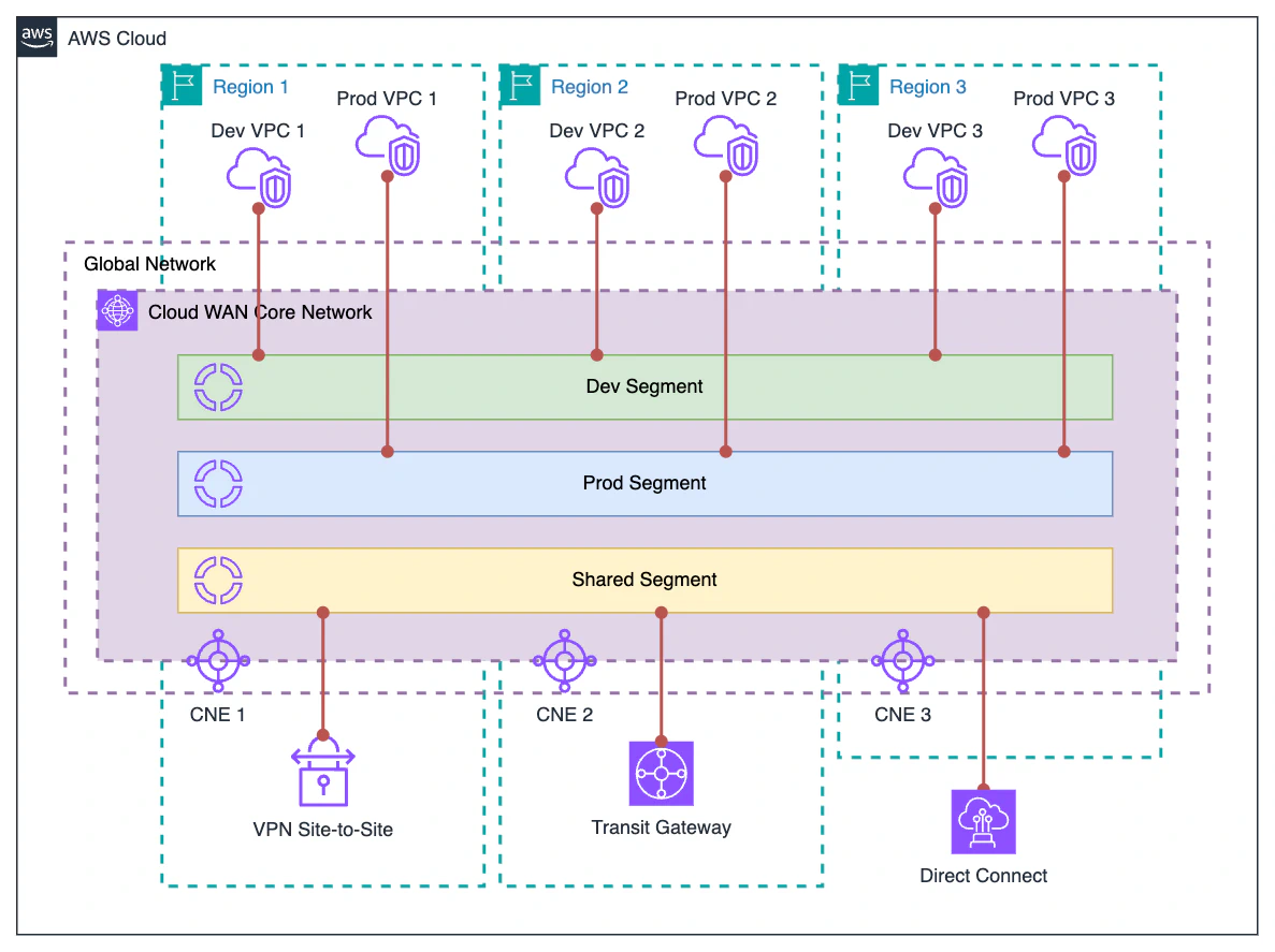
Global Network: High-level logical construct that serves as a container for the Cloud WAN Core Network.
Core Network: Represents the global network managed by AWS. The elements that make up the AWS Cloud WAN infrastructure, such as Core Network Edges or the different attachments, are created on this network.
Attachments: Elements that connect to the Core Network, such as VPCs, VPNs, Transit Gateways, or Direct Connect Gateways.
Core Network Edge: The most important component at the infrastructure level. A Core Network Edge is essentially a router that connects to a specific region; all attachments in that region connect to that Core Network Edge. It is similar to a Transit Gateway in internal operation and characteristics, but Core network edges are managed by AWS, and their configuration is defined by a policy associated with the Core Network.
Logical Components#
Cloud WAN has two main strengths:
It is a global service that allows you to connect multiple regions without the need for complex configurations.
The service configuration is done through policies.
The Core Network Policy is the central configuration element where we define the actual architecture of our Core Network. Let’s look at the main logical components that we can configure using a policy.
Network segments: A segment is a dedicated routing domain. This means that, by default, all attachments within a segment can communicate with each other, while there is no visibility between different segments. This behavior can be modified in the policy document for example, by restricting communication between attachments within the same segment or by sharing a segment’s routes with another segment to allow inter-segment visibility.
Segment actions: This is a configuration section within the Core Network Policy. Segment actions define the behavior of a segment. These actions can include sharing a segment’s routes, configuring static routes, and redirecting traffic for inspection purposes.
Attachment policies: In my opinion, this is one of the best features of AWS Cloud WAN. Attachment policies allow us to assign a particular attachment to its corresponding segment based on tags. While the configuration syntax can be complex, it is extremely powerful. I recommend visiting the attachment policies documentation for more details.
Finally, although we’ve talked about Core Network Edges as an infrastructure component, their definition is actually part of the Core Network Policy configuration.
- Core Network Configuration: This section defines the foundational settings for the Core Network. Here we specify the ASN (Autonomous System Number) range to be used, the CIDR ranges for VPN connections, and, most importantly, the Core Network Edges that the Core Network will deploy.
Sample configuration#
To better illustrate all these concepts, here is a basic sample Core Network Policy.
{
  "version": "2021.12",
  "core-network-configuration": {
    "asn-ranges": [
      "64512-64555"
    ],
    "edge-locations": [
      {
        "asn": 64512,
        "location": "eu-west-1"
      },
      {
        "asn": 64513,
        "location": "us-east-1"
      }
    ],
    "vpn-ecmp-support": false
  },
  "segments": [
    {
      "description": "Segment for demo VPCs",
      "isolate-attachments": false,
      "name": "demo",
      "require-attachment-acceptance": false
    }
  ],
  "attachment-policies": [
    {
      "action": {
        "association-method": "tag",
        "tag-value-of-key": "segment"
      },
      "conditions": [
        {
          "key": "segment",
          "type": "tag-exists"
        }
      ],
      "rule-number": 100
    }
  ]
}
In this policy, we define our Core Network, which will deploy two Core Network Edges in Ireland (eu-west-1) and N. Virginia (us-east-1). We also define a Network Segment called demo.
The last part of the policy defines how attachments are going to be associated with segments. This is a very cool configuration, so let’s dig in a little bit further:
- The
conditionssection specifies that the attachment must include a tag with a key namedsegment. - The
actionsection states that the attachment must be associated with the segment whose name matches the value of thesegmenttag on the attachment.
That way, if we have an attachment with a tag "segment": "demo", it will be associated with the demo segment. However, if the attachment either lacks the tag or has a different value, it won’t be attached unless there is a segment with the same name as the tag’s value.
Demo#
All the theory about AWS Cloud WAN is fine, but the best way to grasp the concepts is through hands-on experience. So let’s get to it with a demo.
The Terraform code to deploy the demo architecture can be found here:
Now, let’s dive into the demo.
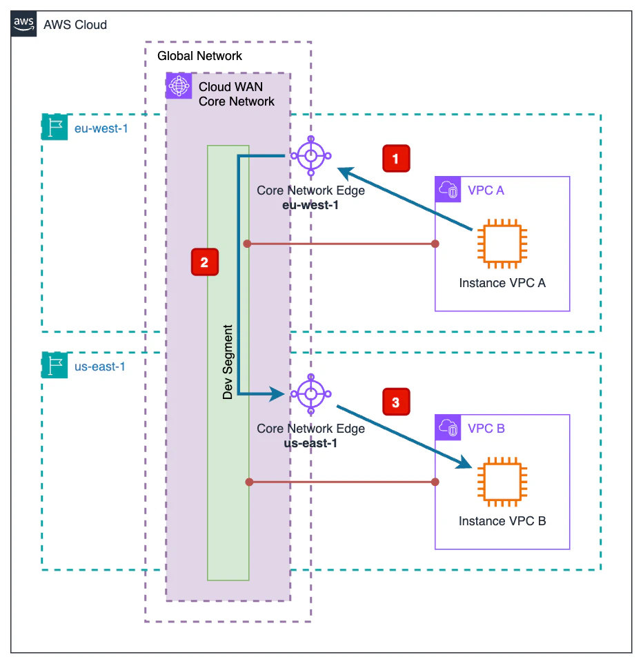
The goal of this demo is to show how an instance located in a VPC in the Ireland region (eu-west-1) can communicate with another instance located in a VPC in the North Virginia region (us-east-1) through AWS Cloud WAN.
As illustrated in the diagram, the path followed by the traffic is as follows:
From the source EC2 instance, traffic exits the VPC and enters the AWS Cloud WAN Core Network through the Core Network Edge in the Ireland region (
eu-west-1).At this point, traffic travels from the Ireland Core Network Edge (
eu-west-1) to the North Virginia Core Network Edge (us-east-1) through the internal AWS network.Traffic exiting the Core Network Edge in North Virginia (
us-east-1) enters the associated VPC to reach the destination EC2 instance.
Now that the goal is clear, let’s begin deploying the infrastructure. To do so, we simply initialize and apply the Terraform code:
terraform init
terraform apply
Once deployed, we can test whether instance B, located in us-east-1, can be reached from instance A, located in eu-west-1, and vice versa.
Connect to instance A trough SSM Session Manager. Once in there we
pinginstance B.sh-5.2$ uname -a Linux ip-192-168-1-20.eu-west-1.compute.internal 6.1.132-147.221.amzn2023.aarch64 #1 SMP Tue Apr 8 13:14:35 UTC 2025 aarch64 aarch64 aarch64 GNU/Linux sh-5.2$ ping -c 10 192.168.1.169 PING 192.168.1.169 (192.168.1.169) 56(84) bytes of data. 64 bytes from 192.168.1.169: icmp_seq=1 ttl=125 time=69.7 ms 64 bytes from 192.168.1.169: icmp_seq=2 ttl=125 time=68.1 ms 64 bytes from 192.168.1.169: icmp_seq=3 ttl=125 time=68.2 ms 64 bytes from 192.168.1.169: icmp_seq=4 ttl=125 time=68.1 ms 64 bytes from 192.168.1.169: icmp_seq=5 ttl=125 time=68.2 ms 64 bytes from 192.168.1.169: icmp_seq=6 ttl=125 time=68.2 ms 64 bytes from 192.168.1.169: icmp_seq=7 ttl=125 time=68.1 ms 64 bytes from 192.168.1.169: icmp_seq=8 ttl=125 time=68.2 ms 64 bytes from 192.168.1.169: icmp_seq=9 ttl=125 time=68.2 ms 64 bytes from 192.168.1.169: icmp_seq=10 ttl=125 time=68.1 ms --- 192.168.1.169 ping statistics --- 10 packets transmitted, 10 received, 0% packet loss, time 9012ms rtt min/avg/max/mdev = 68.104/68.297/69.653/0.452 msAs we can see, instance B is reached from instance A without a problem. It’s worth noting the
pingtimes, which indicate that traffic is flowing between theeu-west-1andus-east-1regions.Now, connect to instance B through SSM Session Manager. Once again, run
pingto instance A.sh-5.2$ uname -a Linux ip-192-168-1-169.ec2.internal 6.1.132-147.221.amzn2023.aarch64 #1 SMP Tue Apr 8 13:14:35 UTC 2025 aarch64 aarch64 aarch64 GNU/Linux sh-5.2$ ping -c 10 192.168.1.20 PING 192.168.1.20 (192.168.1.20) 56(84) bytes of data. 64 bytes from 192.168.1.20: icmp_seq=1 ttl=125 time=69.2 ms 64 bytes from 192.168.1.20: icmp_seq=2 ttl=125 time=68.1 ms 64 bytes from 192.168.1.20: icmp_seq=3 ttl=125 time=68.1 ms 64 bytes from 192.168.1.20: icmp_seq=4 ttl=125 time=68.1 ms 64 bytes from 192.168.1.20: icmp_seq=5 ttl=125 time=68.1 ms 64 bytes from 192.168.1.20: icmp_seq=6 ttl=125 time=68.1 ms 64 bytes from 192.168.1.20: icmp_seq=7 ttl=125 time=68.1 ms 64 bytes from 192.168.1.20: icmp_seq=8 ttl=125 time=68.1 ms 64 bytes from 192.168.1.20: icmp_seq=9 ttl=125 time=68.1 ms 64 bytes from 192.168.1.20: icmp_seq=10 ttl=125 time=68.2 ms --- 192.168.1.20 ping statistics --- 10 packets transmitted, 10 received, 0% packet loss, time 9005ms rtt min/avg/max/mdev = 68.074/68.217/69.203/0.330 msThe results are very similar.
As we’ve seen, with Cloud WAN, connectivity between different regions becomes almost trivial, requiring no manual route management or complex configurations.
If the reader wishes, they can use the provided Terraform code to modify the policy and add new segments and attachments to the Core Network to observe how it behaves.
Remember to destroy the Terraform resources when you’re done with them.
terraform destroy
Wrapping up#
In this post, we’ve covered what AWS Cloud WAN is and what its main components are. We also explored how to configure AWS Cloud WAN using a policy. Lastly, we walked through a demo to see a simple AWS Cloud WAN architecture in action.
This article is the first in a series about AWS Cloud WAN. If you found it interesting, subscribe to the newsletter and be the first to know when the next one is published.
Subscribe