
When working in enterprise environments with AWS, one of the recurring challenges is third-party connectivity: vendors, partners, customers, or even internal legacy systems operating outside your control. In an ideal world, every party would have a unique, well-planned IP address space. In practice, this rarely happens.
The problem is well-known: we cannot guarantee that third-party CIDR ranges won’t overlap with yours. And when there’s overlap, direct IP connectivity simply doesn’t work — routing tables can’t distinguish between a local destination and a remote one if both share the same range.
In on-premises networks, this problem is commonly solved with SNAT and DNAT on a border firewall or router. The device translates source and destination addresses, creating a bridge between two otherwise incompatible address spaces. It’s a mature, well-understood pattern.
How do we bring this pattern to AWS? Historically, the options haven’t been particularly elegant:
- NAT instances: EC2 instances performing NAT manually. Functional, but hard to scale, maintain, and make highly available.
- NLB + PrivateLink: Allows exposing services without overlap, but requires a Network Load Balancer per service, doesn’t easily solve the bidirectional case, and scales poorly when the number of services to expose is high — each service needs its own NLB and endpoint, multiplying costs and operational complexity.
- Complex routing tables with secondary CIDRs: Adding non-overlapping ranges to VPCs and routing through them. Works, but operational complexity grows quickly.
None of these solutions offer a truly cloud-native experience. This is where Amazon VPC Lattice with its VPC Resources capability comes in: a way to expose and consume resources across VPCs that, by design, performs NAT transparently in the service’s data plane.
In this article, we’ll see how to leverage VPC Lattice and VPC Resources to build a full bidirectional NAT pattern that solves the CIDR overlap problem with third parties in a scalable, managed way.
VPC Lattice and VPC Resources#
Before diving into the architecture, let’s review the VPC Lattice components we’ll be using. If you’re already familiar with the service, feel free to skip ahead to the architecture section.
Service Network#
A Service Network is the central logical grouping in VPC Lattice. It acts as a shared connectivity plane to which services, resources, and VPCs are associated. Everything associated with the same Service Network can communicate with each other, subject to the authentication and authorization policies configured.
VPCs can connect to a Service Network in two ways:
- VPC Association: direct association of the VPC to the Service Network. Simple, but only traffic originating within the VPC itself can reach the Service Network — it’s not transitive.
- Service Network Endpoint (SNE): a VPC Endpoint of type ServiceNetwork created in the consumer VPC. Unlike a VPC Association, it allows traffic that arrives at the VPC from outside — through VPC Peering, Transit Gateway, Direct Connect, or VPN — to reach the Service Network resources.
The difference is analogous to VPC Peering versus Transit Gateway: with VPC Peering connectivity is not transitive, while with Transit Gateway traffic from other networks can flow through it. In this third-party use case, where traffic arrives from external networks, the Service Network Endpoint is the necessary option.
An important detail: Service Network Endpoints work independently, without requiring the VPC to have a VPC Association to the same Service Network. This is key to the multi-Service Network isolation model we’ll cover later.
Resource Configuration#
A Resource Configuration defines a specific resource we want to make accessible through the Service Network. Unlike a VPC Lattice Service (which requires target groups, listeners, and rules), a Resource Configuration allows directly exposing:
- An IP address (
ip_resource) - A domain name (
dns_resource) - An ARN of an AWS resource (
arn_resource)
Each Resource Configuration specifies the protocol (currently only TCP) and the port ranges on which the resource is accessible.
Resource Gateway#
A Resource Gateway is the entry point to the resource within the VPC where it resides. It’s deployed in the VPC’s subnets and acts as an intermediary: it receives traffic arriving from the Service Network and directs it to the actual resource.
It’s important to understand that the Resource Gateway is created in the resource provider’s VPC — that is, in the VPC where the service we want to expose is located.
Service Network Endpoint#
The Service Network Endpoint is a VPC Endpoint of type ServiceNetwork created in the consumer VPC. Through this endpoint, VPC clients can access all resources and services associated with the Service Network.
The key difference from a VPC Association is that the Service Network Endpoint allows traffic arriving at the VPC from outside (via Transit Gateway, VPN, Direct Connect, or VPC Peering) to reach the Service Network. With a simple VPC Association, only traffic originating within the VPC itself has access.
The implicit NAT#
And here’s the key to the entire pattern: when traffic flows through VPC Lattice — whether through a Service or a Resource Configuration — the service performs SNAT transparently. The destination resource sees a VPC Lattice address as the source IP, not the client’s real IP.
This means it doesn’t matter if the VPC CIDRs overlap: traffic is never routed directly between them. VPC Lattice acts as an intermediary and translates addresses, exactly as a border firewall would in an on-premises network.
Architecture: the dual VPC pattern with directional Service Networks#
Now that we know the components, let’s see how they combine to solve third-party connectivity.
The architecture is based on two VPCs connected through two VPC Lattice Service Networks — one per traffic direction:
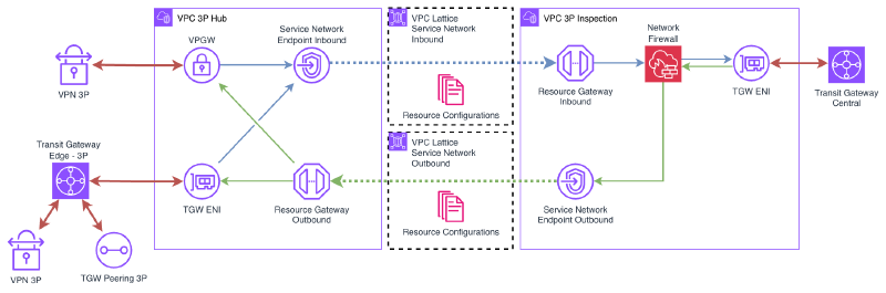
3P Hub VPC#
The 3P Hub VPC is the third-party landing zone. This is where partner, vendor, or legacy system connections terminate:
- Connectivity: Site-to-site VPN, Transit Gateway Peering, Transit Gateway Edge (for Direct Connect) — depending on each third party’s needs.
- CIDR: This is a critical point. This VPC’s CIDR must be compatible with all third parties connecting to it. Several strategies exist:
- Use a CGNAT range (
100.64.0.0/10), which is rarely used in corporate networks. - Use an uncommon private range that doesn’t overlap with known third parties.
- In extreme cases, use a privately-used public IP range (if one is available).
- Use a CGNAT range (
- Size: The VPC can be relatively small. A /24 distributed across two AZs is sufficient for most cases, since it doesn’t host workloads — only connectivity components.
This VPC deploys:
- A Service Network Endpoint connected to the SN Outbound to consume internal services.
- A Resource Gateway that exposes third-party resources. The Resource Configurations associated with this gateway are published to the SN Inbound.
3P Inspection VPC#
The 3P Inspection VPC is the internal side of the architecture. It’s connected to the corporate network through the Central Transit Gateway (or Cloud WAN, depending on the network topology).
This VPC deploys:
- A Resource Gateway that exposes internal services. The Resource Configurations associated with this gateway are published to the SN Outbound.
- A Service Network Endpoint connected to the SN Inbound to consume third-party resources.
VPC Lattice Service Networks#
Unlike a single Service Network model, this architecture uses two directional Service Networks:
- SN Inbound (third-party → internal): contains the Resource Configurations that expose third-party resources. The Resource Gateway in the 3P Hub VPC publishes here, and the SNE in the 3P Inspection VPC consumes.
- SN Outbound (internal → third-party): contains the Resource Configurations that expose internal services. The Resource Gateway in the 3P Inspection VPC publishes here, and the SNE in the 3P Hub VPC consumes.
The separation into two Service Networks is deliberate: it allows complete isolation of traffic flows and, as we’ll see in the multiple third parties section, is the foundation for scaling the pattern to N third parties with bidirectional isolation.
The fundamental point is that there is no direct IP connectivity between the two VPCs. All traffic passes through the VPC Lattice data plane, which performs SNAT transparently. This is what allows both VPCs — and even the third parties behind the Hub VPC — to have overlapping CIDRs without any issues.
Traffic flows#
Let’s look in detail at how traffic flows in each direction.
Consuming a third-party service from the internal network#
When an internal resource needs to access a service exposed by a third party, the flow is:
- Traffic leaves the internal resource and reaches the 3P Inspection VPC through the Central Transit Gateway.
- In the 3P Inspection VPC, traffic is directed to the Service Network Endpoint for the SN Inbound, which sends it to the VPC Lattice Service Network.
- VPC Lattice identifies the corresponding Resource Configuration in the SN Inbound and routes traffic to the Resource Gateway in the 3P Hub VPC.
- The Resource Gateway delivers traffic to the third-party resource. The source IP the third party sees is a VPC Lattice address, not the internal resource’s real IP.
- The response follows the reverse path.
Exposing an internal service to the third party#
When a third party needs to access a service we expose, the flow is reversed:
- Third-party traffic arrives at the 3P Hub VPC through VPN, TGW Peering, or Direct Connect.
- In the 3P Hub VPC, traffic is directed to the Service Network Endpoint for the SN Outbound, which sends it to the VPC Lattice Service Network.
- VPC Lattice identifies the corresponding Resource Configuration in the SN Outbound and routes traffic to the Resource Gateway in the 3P Inspection VPC.
- The Resource Gateway delivers traffic to the internal service. The source IP the internal service sees is a VPC Lattice address, not the third party’s real IP.
- The response follows the reverse path.
In both cases, VPC Lattice acts as a transparent proxy with NAT, eliminating any dependency on each party’s IP address space.
Considerations#
- Latency: VPC Lattice adds an extra hop in the traffic path. In most cases, the added latency is minimal (in the order of milliseconds), but it’s important to consider for latency-sensitive applications.
- Throughput: VPC Lattice scales automatically, but it’s worth reviewing the service quotas to ensure they meet bandwidth requirements.
- Health checks: Resource Configurations don’t have native health checks like Target Groups in a VPC Lattice Service. If you need failure detection, you’ll need to implement it at the application level or through external monitoring.
Demo#
Let’s deploy a demo that illustrates the complete pattern.
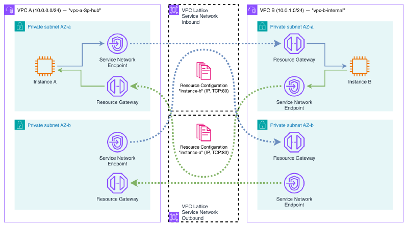
The demo deploys:
- VPC A (
10.0.0.0/24): simulates the 3P Hub VPC. Contains an EC2 instance with a web server (Python HTTP server). - VPC B (
10.0.1.0/24): simulates the 3P Inspection VPC (without firewall). Contains another EC2 instance with a web server. - Two VPC Lattice Service Networks: SN Inbound (VPC A exposes → VPC B consumes) and SN Outbound (VPC B exposes → VPC A consumes).
- Resource Configurations: one per resource (each VPC’s instance), exposing port 80. Each one associated with the Service Network on the consuming side.
- Resource Gateways: one per VPC, to expose the local resource.
- Service Network Endpoints: one per VPC, to consume the remote resource through the corresponding Service Network.
The result is that the instance in VPC A can access the web server in VPC B and vice versa, without any direct IP connectivity between the two VPCs. All traffic passes through VPC Lattice, which performs SNAT transparently.
You can access the demo code here:
Deployment#
terraform init
terraform applyVerification#
Once the infrastructure is deployed, let’s verify that bidirectional connectivity works and that NAT is applied correctly.
vpce-xxx-snra-xxx.rcfg-xxx...vpc-lattice-rsc.region.on.aws. This DNS is publicly resolvable and points to the secondary IPs of the endpoint’s ENIs within your VPC. You can obtain it with aws ec2 describe-vpc-endpoint-associations.Connect to Instance A through SSM Session Manager. This instance is in VPC A (
10.0.0.0/24).First, check the instance’s local IP:
sh-5.2$ hostname -I
10.0.0.137
Now, access Instance B’s web server through the DNS that the Service Network Endpoint assigns to the Resource Configuration:
sh-5.2$ curl http://vpce-0835440315e44ed1a-snra-06828d84e5edce152.rcfg-02071b3b63c375b09.4232ccc.vpc-lattice-rsc.eu-west-1.on.aws
Hello from Instance B (10.0.2.45)
The connection works despite there being no direct IP connectivity between the two VPCs.
Repeat the test in the opposite direction: from Instance B, access Instance A’s web server:
sh-5.2$ hostname -I
10.0.2.45

sh-5.2$ curl http://vpce-0739555d6f9d529a9-snra-03a882c66a1033b4b.rcfg-08c054c34657731be.4232ccc.vpc-lattice-rsc.eu-west-1.on.aws
Hello from Instance A (10.0.0.137)
Bidirectional connectivity works correctly.
Now let’s verify the NAT. From Instance B, run
tcpdumpwhile Instance A makes a request:sh-5.2$ tcpdump -i any -c 5 port 80 -nn 12:59:31.408712 ens5 In IP 10.0.2.166.58602 > 10.0.2.45.80: Flags [S], seq 3388593410, win 62727, length 0 12:59:31.408789 ens5 Out IP 10.0.2.45.80 > 10.0.2.166.58602: Flags [S.], seq 4158802459, ack 3388593411, win 62643, length 0 12:59:31.409942 ens5 In IP 10.0.2.166.58602 > 10.0.2.45.80: Flags [.], ack 1, win 491, length 0 12:59:31.409986 ens5 In IP 10.0.2.166.58602 > 10.0.2.45.80: Flags [P.], seq 1:174, ack 1, win 491, length 173: HTTP: GET / HTTP/1.1 12:59:31.409994 ens5 Out IP 10.0.2.45.80 > 10.0.2.166.58602: Flags [.], ack 174, win 489, length 0The source IP that Instance B sees is
10.0.2.166— the Resource Gateway’s IP in VPC B, not Instance A’s real IP (10.0.0.137). This confirms that VPC Lattice performs SNAT through the Resource Gateway, hiding the real source IP.
Feel free to modify the provided Terraform code to experiment with different configurations: change the CIDRs, add more Resource Configurations, or try DNS-type resources instead of IP.
Remember to destroy the Terraform resources when you’re done using them.
terraform destroyConsiderations and limitations#
Before adopting this pattern, it’s important to consider the following:
TCP only#
As mentioned, VPC Lattice only supports TCP traffic. If your third-party use case requires UDP (e.g., DNS over UDP, SNMP, syslog, or streaming protocols), this pattern is not applicable. In those cases, the alternatives remain:
- NAT instances with iptables/nftables rules for SNAT/DNAT.
- NLB with PrivateLink for specific services (TCP/UDP only, but without the full NAT — SNAT + DNAT — transparency of Lattice).
Service quotas#
VPC Lattice has quotas worth reviewing before scaling the pattern:
- Resource Configurations per Service Network.
- Resource Gateways per VPC.
- Service Network Endpoints per VPC.
Check the current quotas in the official documentation.
Subnet sizing#
Resource Gateways and Service Network Endpoints consume IP addresses from the subnets where they’re deployed. According to the AWS documentation:
“We assign IP addresses to each elastic network interface from its subnet in multiples of /28. The number of IP addresses assigned in each subnet depends on the number of resource configurations and we add additional IPs in /28 blocks as needed.”
In my empirical testing I observed that:
- The Resource Gateway consumes 16 IPs (one /28 block) per subnet by default. However, this value is configurable via the
ipv4_addresses_per_eniparameter on the Resource Gateway. Reducing it to1allows operating with smaller subnets. It does not scale with the number of Resource Configurations. - The Service Network Endpoint (without VPC Association) creates 2 ENIs per AZ, each with 1 IP. This consumption is fixed and independent of the number of Resource Configurations and the
ipv4_addresses_per_enivalue on the Resource Gateway.
The following table summarizes the per-AZ IP consumption observed with the 2N model (without VPC Associations):
| Component | ENIs per AZ | IPs per ENI | Total IPs per AZ | Scales with # of RCs |
|---|---|---|---|---|
| Resource Gateway | 1 | configurable (default 16, minimum 1) | 1–16 | No |
| SNE (without VPC Association) | 2 | 1 | 2 | No |
| Total Lattice | 3–18 |
/24 or smaller), set ipv4_addresses_per_eni on the Resource Gateway to a low value (e.g., 1). The default of 16 consumes a full /28 block per subnet, which can quickly exhaust available address space.Comparison with PrivateLink + NLB#
| PrivateLink + NLB | VPC Lattice SNE | |
|---|---|---|
| NLB required | Yes (one per service) | No |
| Endpoints required | 1 per service | 1 for all services |
| Transparent NAT | No (DNAT only) | Yes (full SNAT + DNAT) |
| Transitive (VPN/TGW) | No | Yes |
| Subnet sizing | 1 IP per endpoint per AZ | Requires larger subnets (see note above) |
VPC Lattice simplifies operations and offers transparent NAT with transitivity, but consumes more IP address space than classic PrivateLink. It’s a trade-off to consider in environments with IP addressing constraints.
Costs#
VPC Lattice costs consist of:
- Hourly cost for VPC Endpoints (ServiceNetwork type) and Resource Gateways.
- Per-GB cost for processed data.
For high-traffic scenarios, it’s worth comparing VPC Lattice costs with alternatives like NAT instances (EC2 cost) or NLB + PrivateLink (NLB + PrivateLink hourly and per-GB cost).
Multiple third parties and isolation#
When dealing with multiple third parties, the need to isolate them from each other arises. Within a single Service Network, all Resource Configurations are visible from all Service Network Endpoints connected to it. Additionally, Service Network auth policies do not apply to Resource Configurations. This means it’s not possible to segment access at the resource level within a single Service Network.
The solution is to use separate Service Networks per third party — specifically, 2 Service Networks per third party (one per direction), following the same directional model from the base architecture:
3P-A: SN-Inbound-A  (3P-A exposes → internal network consumes)
      SN-Outbound-A (internal network exposes → 3P-A consumes)

3P-B: SN-Inbound-B  (3P-B exposes → internal network consumes)
      SN-Outbound-B (internal network exposes → 3P-B consumes)
Each third party only has visibility into its own Service Networks. Third party A cannot see third party B’s Resource Configurations because they live in completely separate Service Networks.
The internal VPC creates Service Network Endpoints to each SN Inbound to consume each third party’s resources, and publishes its services to each SN Outbound via Resource Configurations. Each third-party VPC only has an SNE to its SN Outbound and a Resource Gateway publishing to its SN Inbound.
This model works because Service Network Endpoints do not require a VPC Association. A VPC can create SNEs to multiple Service Networks without restrictions, allowing the internal VPC to connect to as many third parties as needed.
For N third parties, the model requires 2N Service Networks, N SNEs in the internal VPC (one per SN Inbound), and the internal service Resource Configurations replicated in each SN Outbound. Operational cost grows linearly, but isolation is complete.
Wrapping up#
In this article, I’ve shown how VPC Lattice and VPC Resources allow you to solve the classic CIDR overlap problem in third-party connectivity in a cloud-native way. The dual VPC pattern with directional Service Networks, Resource Gateways, and Service Network Endpoints provides full bidirectional NAT without needing to manage NAT instances, complex routing tables, or additional network appliances.
The key to the pattern is that VPC Lattice acts as a transparent intermediary, performing SNAT on all traffic passing through its data plane. This eliminates the dependency on IP address space and allows connecting networks with overlapping CIDRs in a fully managed way. And because Service Network Endpoints work without VPC Associations, the model scales to multiple third parties with complete isolation using 2 Service Networks per third party.